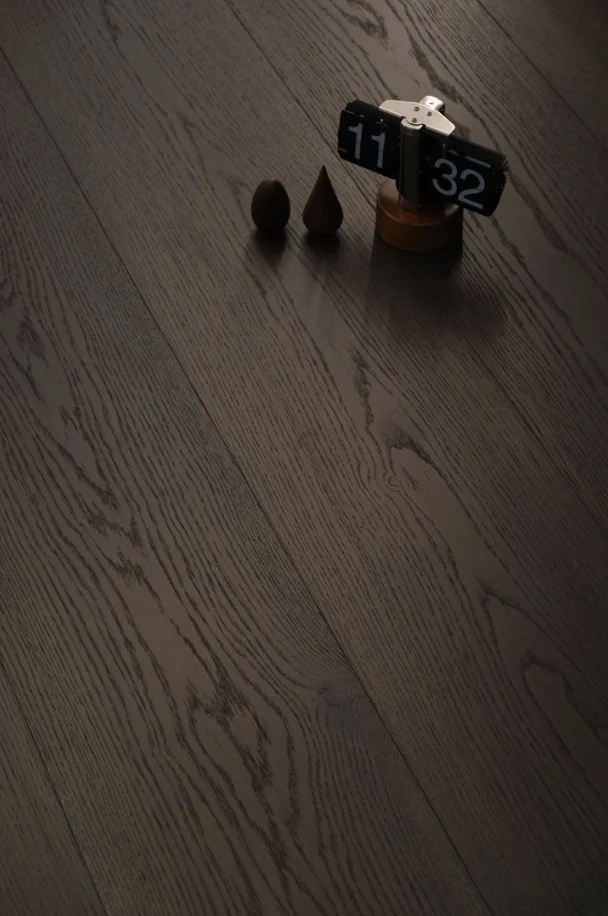















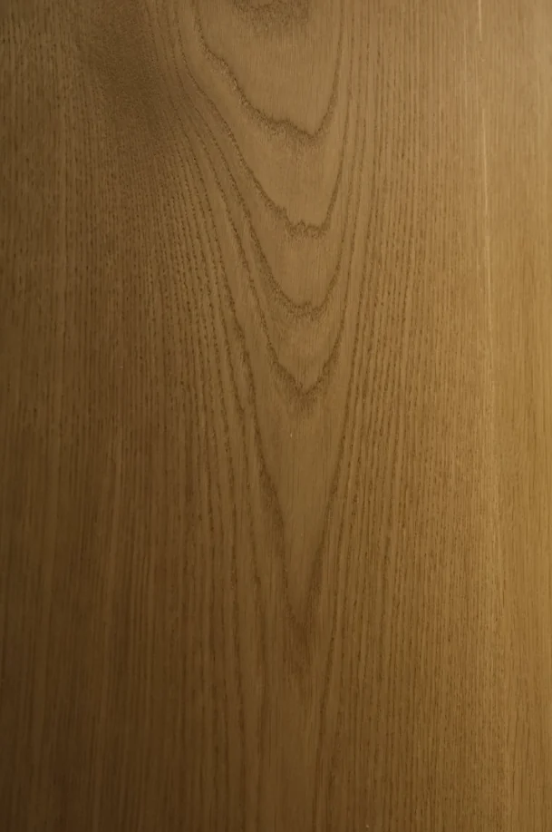
Corridors bring several flooring relationships together: entrances, bedroom doorways and living areas may have different axes. Mark circulation and doorways first, then compare clear continuous or turning options. HUAGE's formats and patterns provide references without one direction rule for every home.
First identify the key relationships to retain throughout the home
Mark entrances, corridors, principal rooms and fixed cabinetry on plans, trying continuous directions and room-specific adjustments. Examine visible flooring at doorways, corridor ends and furniture to identify the relationship that supports the scheme. Direction need not follow every room's longest side; control lines and turns need clear reasons.
For herringbone or chevron, use actual board dimensions to assess the pattern through doorways. Their board-end relationships differ; rotating the same texture image is insufficient. If the product is not fixed, retain a preliminary illustration, then update the layout once the specification is confirmed so the final drawings correspond to the real material.
Visual continuity does not eliminate technical boundaries
Visual continuity must be checked alongside product and installation conditions. Actual divisions, perimeter allowances and material transitions are determined by the installation proposal. A wish to hide trims does not remove necessary construction details. The installation methods in the original catalogue provide discussion references with different conditions of use; one figure must not be applied to every room and environment throughout a home.
Define how local direction changes occur: at doorway boundaries or through patterns or trims. Enlarged details should show end boards, centrelines and neighbours before installation. Different constructions or thicknesses need separate level and connection checks even if colours match; matching colour cannot replace details.
Create a direction diagram that supports collaboration
Approved plans can show material identifiers, starting lines and direction arrows for each zone, with matching/different samples. Later room revisions can then trace corridor relationships. Calculate quantities from the full layout and cuts, not continuous visual area or a universal wastage promise.
HUAGE catalogue information helps locate options; current supply configurations and UK installation conditions require project approval. Matching plans, samples and details lets procurement and installation follow the same decision. Both continuity and changes in direction may be appropriate when they respond to the actual space rather than copy another photograph's orientation.